Origin as a Tool for Studying Train-Handling Procedures
Problem
A large freight train suffered a “break-in-two” upon startup after stopping on a slight grade. The client requested an analysis.
Solution
Using data supplied by the client, simulations were run and the data were output to Origin for graphical presentation of results.
“I use Origin daily on almost every project.”
Jack Chislett of TÜV Rheinland Mobility Rail Sciences Division investigates train derailments and performs other train studies for most of the major railroads in the country. Jack has been an Origin user since the early 1990s and has found Origin’s graphing and data analysis capabilities to be an essential part of his investigative work.
“Origin has a consistent interface across most graph types. The ability to synchronize multiple graphs by linking the X axes is very important. I use the analysis routines for interpolation and extrapolation. I occasionally use the 3D and contour graphs to show train forces leading up to derailments.”
Recently, Jack was given the job of investigating a “break-in-two” that occurred during throttle-up on a long freight train. Working from client-supplied event recorder data (the railroad equivalent of the “black box”), track profiles and train consists, Jack performed data pre-processing before inputting data to industry-standard simulation models. Results were then output to Origin for further graphical analysis and presentation.
“We were able to show multiple variables on one graph, including the track profile, train handling, speeds and calculated forces. This allowed the client to see the effect of each variable on the others.”
The train, in this case, consisted of three locomotives, 56 loads, 36 empties, weighed 7433 tons and was 6745 feet long. The train had stopped on a slightly ascending grade, just short of a grade crossing. Upon startup, the 13th head car suffered a broken knuckle and the train became separated, an event known in the industry as a “break-in-two.”
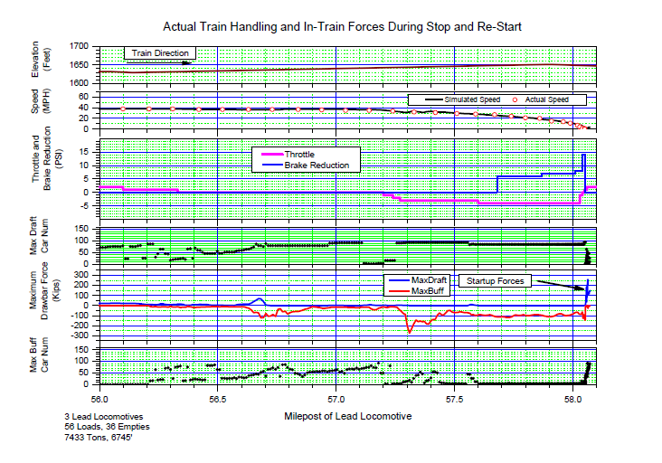
What is clear from the graph of Maximum Drawbar Force, above ("MaxDraft" plot, far right end), is that there was a rapid increase in force applied at the drawbar on train startup. It was speculated that the mode of braking and the slightly ascending grade, were possible factors in the knuckle failure.
Trains typically rely on some combination of three braking systems(1) (a) dynamic braking, which entails use of the locomotives’ electric motors to dissipate energy, (b) the air-braking system that operates throughout the train and (c) the independent brakes on board the locomotives. In the break-in-two case, event recorder data confirmed that a combination of dynamic and air-braking was used to stop the train prior to the break-in-two.
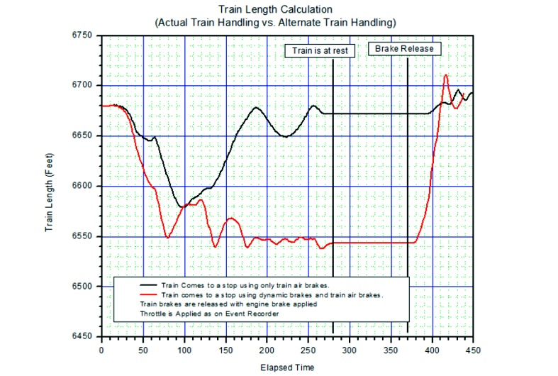
Thus, the client requested simulation of an alternate case in which locomotives were kept under light throttle during the stop, while braking was accomplished by train air-brakes only. The analysis showed that under these conditions the train would have come to rest in a lightly stretched state. In contrast, simulations of the actual case in which the train was stopped using a combination of dynamic and air-braking, showed the train coming to rest in a bunched state (following figure).
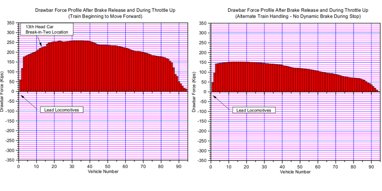
In this bunched state, the release of the brakes just prior to throttle-up had the effect of causing each car to roll backwards just as the locomotives were applying force in the opposite direction. This amplified the forces being applied to each car and led to the failure of the knuckle on the 13th head car. The following column plots show simulated drawbar force profiles for the actual case (left) and the alternate case (right). What these plots clearly show is that the drawbar forces on throttle-up would have been much greater in the actual case in which the train had been previously stopped using a combination of dynamic and train air-brakes.
Summary:
- A train had made a stop on a slightly ascending grade short of a grade crossing. After brake release and on throttle-up, the knuckle of the 13th head car failed, resulting in a “break-in-two.”
- Longitudinal force simulations made using a transportation industry standard model indicated that the use of both dynamic and train air-brakes caused a bunching of the train. When, prior to throttle-up, the brakes were released, the train cars rolled backwards on the slightly ascending grade, creating and amplifying high runout forces and leading to drawbar breakage when the locomotives were throttled up.
- Simulations of an alternate braking case wherein locomotives were kept in light throttle while only train air-brakes were applied, produced a lightly stretched train and subsequently, a much lower and more static force distribution at the drawbar, across all cars.
1. US Department of Transportation. Safe Placement of Train Cars: A Report. 2005.